Automated Optical Inspection Machines: Insights Into Automated Quality Control
In modern manufacturing, even a small defect can affect product reliability, production efficiency, and customer satisfaction. Automated Optical Inspection (AOI) machines help manufacturers identify visible defects by capturing images of components and analyzing them against defined quality criteria.
These systems are widely used in electronics manufacturing, particularly for inspecting printed circuit boards (PCBs), solder joints, component placement, and surface conditions. As production lines become faster and product designs more compact, manual inspection alone can struggle to deliver consistent results at high volumes.
Understanding how automated optical inspection works helps explain its role in modern quality control. From cameras and lighting to image-processing software and defect classification, each element contributes to identifying manufacturing problems before products move to the next production stage.
How Automated Optical Inspection Machines Work
An AOI machine uses cameras, controlled lighting, image-processing software, and inspection algorithms to examine a product without relying entirely on human visual judgment. The system captures images of selected areas and analyzes them for differences from expected characteristics.
Depending on the application, the reference may be a known-good image, a computer-aided design file, predefined measurement limits, or a set of programmed inspection rules. The software evaluates the captured image and identifies features that may indicate a defect.
When the system detects a potential problem, it can flag the location for review, record the result, or send a signal to the production line. The exact response depends on how the inspection equipment is integrated into the manufacturing process.
AOI does not physically repair defective products. Its primary role is to detect and classify visible problems so that manufacturers can investigate them and decide what action is necessary.
Key Components Behind Inspection Accuracy
The performance of an AOI machine depends on several interconnected components. A limitation in one area can affect the quality of the overall inspection.
Industrial cameras capture images of the product. Camera resolution, sensor characteristics, lens quality, and image capture speed influence how clearly the system can identify small features.
Lighting systems make defects easier to distinguish from normal product characteristics. Different lighting angles and intensities can reveal scratches, raised edges, solder irregularities, surface contamination, and other visual differences that may be difficult to detect under ordinary lighting.
Image-processing software analyzes the captured images. It may use geometric measurements, pattern matching, color analysis, rule-based algorithms, or machine-learning models to identify irregularities.
Motion systems and conveyors position products consistently beneath the cameras. Accurate positioning helps the software compare images reliably, especially when inspecting small electronic components at high speed.
Together, these elements allow AOI equipment to perform repeatable inspections across large production volumes.
Where AOI Machines Fit Into Electronics Manufacturing
Automated optical inspection is particularly valuable in electronics manufacturing because printed circuit boards contain numerous small components, fine solder connections, and tightly controlled placement requirements.
After surface-mount technology equipment places components onto a PCB, AOI can inspect whether components are present, correctly positioned, properly oriented, and visually consistent with the programmed reference.
Depending on the machine and inspection stage, it may detect missing components, misalignment, polarity errors, solder bridges, insufficient visible solder, lifted leads, or other observable defects.
AOI is also used after soldering operations. At this stage, inspection can reveal visible problems associated with solder joints, component placement, and assembly quality.
However, optical inspection has limitations. A conventional two-dimensional system may struggle to evaluate hidden connections beneath certain components or identify internal defects that do not produce visible surface changes. Manufacturers may use X-ray inspection or other testing methods when internal structure or concealed solder joints must be examined.
Different Inspection Approaches and Imaging Techniques
AOI systems vary according to the products being inspected and the characteristics that must be measured. The appropriate configuration depends on defect size, surface geometry, production speed, and inspection requirements.
Two-Dimensional Optical Inspection
Two-dimensional AOI analyzes flat images to identify differences in color, shape, position, and visible surface characteristics. It is commonly used for checking component presence, alignment, orientation, markings, and certain solder-related defects.
Its effectiveness depends on image quality and the visibility of the feature being inspected. Reflective surfaces, shadows, overlapping components, and inconsistent positioning can complicate analysis.
Three-Dimensional Optical Inspection
Three-dimensional inspection adds height or surface-profile information to the analysis. Depending on the technology, systems may use structured light, laser triangulation, or other optical measurement techniques to estimate surface geometry.
This additional information can help evaluate solder-joint shape, component height, coplanarity, and other characteristics that cannot be assessed reliably from a flat image alone.
Three-dimensional inspection does not eliminate every limitation. Measurement accuracy still depends on the equipment, surface properties, calibration, and inspection setup.
Rule-Based and AI-Assisted Inspection
Traditional AOI systems often rely on programmed rules and predefined thresholds. These methods can be effective when products have stable designs and acceptable variations are well understood.
Some newer systems incorporate machine learning to distinguish genuine defects from harmless visual variations. Depending on the implementation, AI-assisted classification can help reduce unnecessary alerts, but it requires appropriate training data, validation, and ongoing performance monitoring.
Neither approach is automatically accurate in every situation. Inspection performance must be established against real production conditions and known defect examples.
Why Inspection Accuracy Requires Careful Setup
An AOI machine can generate incorrect results even when its cameras and software are functioning normally. Inspection accuracy depends on how well the system understands the product and distinguishes acceptable variation from genuine defects.
A false positive occurs when the system flags an acceptable product as defective. Excessive false positives can increase manual review, interrupt production, and reduce confidence in automated inspection.
A false negative occurs when a genuine defect passes inspection without being detected. This can allow defective products to continue through manufacturing or reach later production stages.
Lighting changes, surface reflections, camera calibration, product variation, and incorrect inspection thresholds can contribute to these errors. Manufacturers therefore need carefully designed inspection recipes, appropriate reference images, and regular verification.
When a new product or PCB layout enters production, the inspection program may require additional development and validation. Changes in component design, solder materials, or production conditions can also affect inspection results.
Integrating AOI Into a Production Line
AOI equipment provides more value when inspection results are connected to the wider manufacturing workflow. Rather than operating as an isolated checkpoint, the system can exchange information with production equipment, manufacturing execution systems, and quality databases.
For example, repeated detection of a particular solder defect may prompt engineers to examine solder paste deposition, component placement, reflow settings, or material handling. The inspection result identifies a possible problem, while process analysis helps determine its underlying cause.
Inspection records can also support traceability by linking defect locations and inspection outcomes to production batches, machine settings, or product identifiers. The level of traceability depends on the equipment and factory software integration.
Effective integration requires clear rules for handling rejected products, reviewing uncertain results, and returning corrected products to the production process. Without these procedures, automated detection may create alerts without producing meaningful quality improvements.
Measuring AOI Performance Over Time
Manufacturers need more than a machine's advertised inspection speed to understand its practical value. Useful performance measures include defect detection rates, false-call rates, inspection coverage, throughput, and the time required to review flagged products.
These measures should be evaluated together. A system that inspects products quickly but misses important defects may not meet the factory's quality requirements. Similarly, a highly sensitive system that flags too many acceptable products may create excessive review work.
Regular audits using known-good products and representative defect samples can help verify that the inspection program remains reliable. Engineers can also compare AOI results with findings from downstream testing, manual review, or other inspection technologies.
This ongoing evaluation helps manufacturers adjust inspection rules and identify changes in product quality or production conditions.
Frequently Asked Questions
What does an AOI machine inspect?
An AOI machine examines visible product features such as component placement, solder appearance, surface defects, alignment, and markings. Its inspection capabilities depend on the imaging technology and programmed criteria.
Can AOI machines replace manual inspection?
AOI can automate many repetitive visual checks, but manual review remains useful for investigating uncertain results, validating inspection programs, and evaluating defects that automated systems cannot classify reliably.
What is the difference between 2D and 3D AOI?
Two-dimensional AOI analyzes flat images, while three-dimensional AOI also measures surface height or geometry. Three-dimensional information can help detect certain structural variations that are difficult to assess using conventional images alone.
Can AOI detect every manufacturing defect?
No. AOI primarily identifies defects that can be observed through its optical setup. Hidden solder connections, internal damage, and some electrical faults may require X-ray inspection, electrical testing, or other specialized methods.
How can manufacturers improve AOI results?
Consistent lighting, correct calibration, validated inspection programs, suitable defect thresholds, and regular performance checks can improve inspection reliability. Reviewing false positives and missed defects also helps refine the system over time.
Conclusion
Automated Optical Inspection machines support modern quality control by combining industrial imaging, controlled lighting, image analysis, and production-line integration. They help manufacturers identify visible defects consistently and generate inspection data that can support process improvement.
Their effectiveness depends on selecting suitable imaging technology, configuring inspection criteria carefully, and monitoring performance under real manufacturing conditions. When integrated with broader quality systems, AOI becomes more than a defect detection tool: it helps manufacturers understand production variation and make better-informed quality decisions.

Related Post...
Fluid Pump Systems Discover How Modern Industries Improve Flow Efficiency
Updated: July 22, 2026
Read More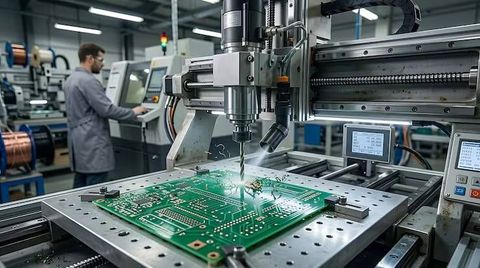
Printed Circuit Board Assembly Plants: Explore the Electronics Manufacturing Process
Updated: October 02, 2026
Read More
Sheet Cutting Machines Explore How Industrial Cutting Methods Work
Updated: September 07, 2026
Read More